Wednesday, September 29, 2021

Lupine Publishers| The Use of Tin Plague in The Analysis of Pure Tin

 Lupine Publishers| Modern Approaches On Material Science

Abstract

Study focuses on the basis of knowledge the mechanism of the process βSn  αSn for use it to analysis of important material for science and technology. The possibility of ultra-high purity Sn to analyse by measuring the rate (V) of the allotropic changing (V βSn  αSn) is investigated. Metals of such high purity are inaccessible to chemical method, so analyzed by method of a residual resistance at temperature (T) of liquid He, inaccessible to most enterprises. The method gives an estimate of the total content of impurities. For Sn with low T of βSn αSn) due to the simplicity of the measuring purity by the V (βSnαSn) is tempting. In high purity Sn with a low content of impurities, this method seems more accessible and convenient than others and probably possible. This paper proposes the affordable and simple method of analysis, high sensitivity, accuracy and reproducibility of the results. not inferior to the complex method of measuring the residual resistance.

Keywords: Residual Resistance; Phase Transition Rate; Impurities

Introduction

The World made 7 metals, according to the 7 planets. (Navoi). In the table of ranks of the ancient Sn is pair to Jupiter, the largest planet. And now Snwith the honorary № 50 in the center of the Periodic Table of Mendeleev. Sn is the oldest to man known metal. Aristotle knew about the Sn plague, but didn’t know that it was a consequence of the allotropic transformation of Sn white to gray, β®α. The nebulous mysteries of Sn plague infection accumulated interests many centuries tothis phenomenon.A main Interest in βSn®αSn appeared after the evidence [1,2]Goryunova semiconductor nature of αSn with covalent bond by changing the metal bond to covalent, the electronic structure s2 p2βSn to sp3,tetragonal structure with

KN=6 to a cubic structure with KN=4 with bonds to the vertices of tetrahedrons ofαSn.These principlescreating of semiconductor compounds ofneeds properties. To turn into metastable αSn except T below 12.4oC,is a necessary [2] seed withthe parameters of the bond and structures related αSn and its contact with tin.The nearest neighbors of Sn give a compounds InSb and CdTe, There, pairs of atoms give in sum of total electrons the same as 2 atoms of Sn and parameters of structures [1] almost the same of αSn. InSb, CdTe, αSn the better seed of Sn®αSn, but in contrast to metastable αSn powder, InSb, CdTe are strong solid crystals. Theinfection is caused by atomic contact with a seed. Tin always covered by protective film of SnO2which don’t allow contact.If the seed is placed on the surface of Sn, there is Infection!? And from inert substances that had contact previously with the seed although it now removed[3]. Solid crystals recognized the past! Infection at a distance is possible too![4]. It was quite misunderstood: what gives an information from the seed? Necessary presence of the air, atmosphere.There is Ic agent,[5-7] Inthe vacuum, dryvessel, or after treatment of the inert substance with any solvent of water, so there is no infection,Ic is a carrier from the seed. Metastable structure Ic in the size of nanoparticles can growing epitaxially on the related structure, penetrate through the microdefects of the protective SnO2. So, it is clear that infection under water which absorbed the Icnanoparticles is impossible.This opinion turned out to be wrong. With a very small probability for a time more a year under moving water, infection occurs, and this valuable phenomenon gives ways to many practical tasks andunderstanding of life processes[7].The source of infection has been found. and yet another unexpected source of infection was found. This is property for practical aim. Tin remember about stay in the αSn phase. There is a βSn®αSn transition and back αSn®βSn, due to a change of .>/<d by 26.6%.volume effect. At each β®αmovedecreased d and at α®βd increased. So without external tools Sn gives pure powder of any size particles[8,9].

Knowing the Icas seed allows to use for solving a row of other practical problems [5-7]with use of the terrible plague by a simple way [10,11] in forms convenient for creating p/n shifts , simple effective purification of Sn without meltingin solid phase [12].Method of zone melting [13] to purification is determined by the difference in the K, ratio of the solubility of impurities at the phase boundary. At melting metal doesn’t change type of the bond on the border ofsolid/liquid, soK is near to 1, the difference is knowingly less than at of the metal /semiconductorboundary with the great differences in the nature of their chemical bonds, CN (coordination number), structures. The cleaning efficiency at the border metal /semiconductor, K far from1. And so was a reason that zone melting became widely used when there was a need in semiconductors of high purity.A knowledge of the mechanism of the solid-phase process of βSn ®αSn [7] land to opinionof possibility to apply it in the analysis of the height purity of Sn.

Theoretical View on The Possibility of Analyzing by V Βsn→Αsn

Analysis of high-purity materials is labor-intensive and often impossible if the sensitivity of classical methods is insufficient [14]. There is a method for measuring the g4.2К, i.e. the ratio R 300K /R 4.2 K, method of residual resistance, which gives an estimate of the amount of impurities in metals [15] of high purity. The residual resistance of Sn at 4.2 K before the transition to the superconducting state depends on its purity and perfection of structure. The R at T of room is almost constant, and the g4.2К, i.e. the ratio R 300K /R 4.2 K, is residual R characterizes the purity of Sn.The purer the metal and more perfect its structure, the lower the R at 4.2 K and the higher the value g4.2К, which serves as a measure of the total content of impurities in metals. But measuringequipment is difficult, and liquid He is rarely available to the most of organizations. Studies of allotropic transformation of Sn [5-7] showed a connection between the purity by g4.2К, and the rate V of its phase transformation into αSn. But also, it seemed unrealistic to use it for analyses after bright experiments [16] showed the impurities in Sn are accelerating, indifferent and inhibiting. Hence, the analysis of the purity of Sn by V βSn®αSnis impossible at it depends on the ratio of concentrations of dissimilar impurities. But the mechanismof distinguishing the role of impurities is not clear at all. If each atom of the impurity violates the g4.2К, of the metal, which theg4.2Кmethod illustrates by analyzingany other metals, why the impurities of different metals differ in their effect on the V βSn®αSntransition. This became clear when we knew the mechanism of infection with the "tin plague" [4]. In [16] was studied Sn not of high purity, there are no errors in experiments. The chaotic nature of the dependences of V on purity is clearly shown [5,7]atstudying the influence of impurities on V of βSn ®αSn. The fact is that the commonly zone melting is powerless to clean from Sb because it has K=1 in Sn. The solubilities of Sb in solid and molten Sn are the same, And the Sb impurity on both sides of the phase boundary is the same and so can’t to be redistributed, as other impurities with K≠1.And in the ores of Sn impurity in the Sb usually dominates. At zone melting cleaning, the Sb impurityalways prevails over the others. And Inhimself like of all metals is inhibitory too by the same reasons, but it was shown as accelerator [16] because In+Sb gives the best seed InSb. And in the Sn of high purity, the impurity of In, like any impurity, individual. But having the knowledge aboutthe dependence of the βSn ®αSnprocess on many factors, it is necessary to observe the requirements 1-4, understood during the experiments for creating a method for analyzes[17].

Experimental Part

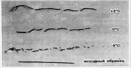
It is possible to create a method for analyzing the purity of V βSn → αSn similar to measurements of residual resistance, suitable for high-purity metals. Previously, it was found [3,5,7] that the dependence of V βSn → αSn on T for any samples has a maximum. This is very easy to understand. At low T with its growth V βSn → αSn grows according to the Arrhenius equation. V cannot grow constantly, because as it approaches the point of the phase transition, it becomes smaller and turns to 0. When infected, Sn crumbles into an arc-shaped powder, making difficult to measure phase shift lengths. Amorphous wires of fast quenching, single crystals of βSn and even annealed wires with slow infection remain almost the original shape but with some bending, and break at V βSn→αSn depending on the T (Figure 1) to parts of different lengths, but almost the same at each T. Accumulation of impurities by the method of residual resistance was recorded in the fracture. It is seen that after the fracture, the sections at each T are close to each other. For analysis, it is necessary that the content of impurities is constant along the length, that is, choose V βSn → αSn for it, V of growth of αSn and V of impurities were now equal, and Sn maintain the solidity too.

Figure 1: Fracture of Sn of different purity with the accumulation of impurities overtaking the phase boundary at its low V. T= +2:0 and -5 ̊С.
Lupinepublishers-openaccess-material-science-journal

Requirements

1) Monoliths are obtained for the growth of αSn [10,11] in the ice shape. The study of a movement of impurities at βSn → αSn allowed us to create a method like of zone cleaning in a solid, but for analysis it is necessary that the content of impurities is constant along the length, that is, choose V βSn→αSn and V of impurities equal and maintain the solid state.

2)Monoliths are obtained by standard preparing a Sn for analysis, so its behavior and structure depends on the previous mechanical and thermal history of Sn. Ins sample in standard quartz formsmelted and cooled under standard vacuum conditions, then Sn melt poured into a SiO2 mold to made identical samples in the form of wire or rod with a spherical surface of one edge of it, then annealed and cooled in vacuum.

3)To create the minimum of seeds by moving of H2O near of the contact Sn of spherical surface of edge with polishedor spherical surface of InSbseed.in thermostat with selected T for analysis.So, to create the minimum of seeds by moving of H2O near of contact Snwith InSb in thetermostat with ice nearly of chooses T.

4)The diagram of calibration dependence of V βSn®αSn / g4.2should be attributed to the same strictly selected T for analysis.

5)The infection V should be measured repeatedly for graphical correction of errors in a visual determination of the length of the infected area. At T, chosenfor aphase transition the impurity does not accumulate, and the concentration along the entire length is constant, which is important for analysis. For the integrity of the sample, it is possible to infect as in [10,11].You can make many measurements V βSn®αSn on length, reducing the measurement error statistically. The sections along the path of the Snwhite – dark border is measured repeatedly over time. After the end of the analyze measurement with standard remelting, the αSn is converted to βSn, especially if the analysis result must be checked by direct measurement g4,2K, which is applicable only f or metals. According to the graph for a given analysis at T V βSn ®αSn from g4,2Kfind the purity of Sn. Measures of V different samples gave 1.37 and 1.41 mm/hour, corresponded to g4,2K47 500 and 55 000. Control analyses of them give g4,2K46,800 and 55,400. Errors of 1.5% and 0.8% within the measurement accuracyof V and g4,2K. And to check the reproducibility of results in 10 standard samples, an infection V was measured on the same day in the same thermostat. The average of a value of V is 1.48 mm/ hour. A maximum deviation V valueof one sample was 1.46 mm / hour, which is 1.3%, all the others gave 1.48, 149, 1.47.

Summary

By using for the practical aims of “terrible tin plague” along with its application to obtain pure powders of a given dispersion, for further purification of high-purity tin, for growing profiled crystal of a unique material αSn even with p/n transition, simple accessible method of purity Sn analysis was created, which seemed fundamentally impossible. The accuracy and reliability of the results of the proposed method with obvious availability, accessibly and simplicity even is not complicated and complex method of residual resistance without using of liquid helium. Here is only whether the method can be considered created until it still not published and not known to researchers, for whom, and not for corrupt officials, this work was done.

Gratitude’s

The author is grateful to V. V. Ryazanov for his help in measuring g4.2K- residual resistance and for his constant interest in the work, advice and discussions and cooperation with N. G. Nikishina, R. A. Ohanyan , Efremov A.S, Boronina L.R. , Sidelnikov M.S.

For more Lupine Publishers Open Access Journals Please visit our website:

 wt u have given that link add For more Modern Approaches on Material Science articles Please Click Here:

https://lupinepublishers.com/material-science-journal/

Friday, September 3, 2021

Lupine Publishers| Strength Improvement and Interface Characteristic of Dissimilar Metal Joints for TC4 Ti Alloy to Nitinol NiTi alloy

 Lupine Publishers| Modern Approaches on Material Science

Abstract

Laser welding of TC4 Ti alloy to NiTi alloy has been applied using pure Cu as an interlayer. Mechanical properties of the joints were evaluated by tensile tests. Based on avoiding the formation of Ti-Ni intermetallics in the joint, three welding processes for Ti alloy-NiTi alloy joint were introduced. The joint was formed while the laser was acted on the Cu interlayer. Experimental results showed that Cu interlayer was helping to decrease the Ti-Ni intermetallics by forming Ti-Cu phases in the weld. The average tensile strength of the joint was 216 MPa.

Keywords: Ti alloy; NiTi alloy; Cu interlayer; Laser welding; Microstructure; Tensile strength

Introduction

TiNi alloy has shape memory and pseudo-elastic properties, excellent corrosion resistance and good biocompatibility, it provides promising solutions to solve the problems in various applications such as aerospace, atomic energy, microelectronics, and medical equipment [1,2]. As we all know, the successful application of any advanced material depends not only on its original properties, but also on its development [3]. People are more and more interested in the combination of TiNi alloy and other materials, especially for the development of devices with different mechanical properties and corrosion resistance. Ti alloy has excellent comprehensive properties, such as high specific strength, high specific modulus, hardness, corrosion resistance and high damage resistance [4,5]. It is widely used in aerospace, marine industry, biomedical engineering, and military industry. The composite materials of TiNi alloy and Ti alloy can not only meet the requirements of heat conduction, conductivity, and corrosion resistance, but also meet the requirements of high strength but light weight [6]. Therefore, it will be widely used in aerospace, instrumentation, electronics, chemical industry, and other fields. Compared with single material property, this material can use the performance and cost advantages of each material to select the best material for each structural component [7]. However, the weldability of dissimilar materials also limits the wide application of these alloys. This leads to the formation of brittle-like intermetallic compounds (IMCs) in the weld zone. For example, Ti2Ni, NiTi, Ni3Ti [8]. The formation of Ti-Ni IMCs in the weld makes the weld brittle, and the mismatch of the thermal expansion coefficient of the two materials, it will lead to the formation of transverse cracks in the weld and the deterioration of mechanical properties [9-11]. In fact, TiNi alloy-Ti alloy joint is one of the most direct and effective methods to increase the use of TiNi alloy, Ti alloy and other lightweight materials in the field of aerospace and engineering manufacturing and to use structural lightweight design to achieve structural optimization, energy saving, environmental protection and safety [12]. Therefore, the effective connection between TiNi alloy and Ti alloy becomes an urgent problem.

At present, the most commonly used method is to insert an intermediate layer to improve the microstructure of the joint, which can improve the mechanical stability between TiNi alloy and Ti alloy and lead to the formation of other phases except for Ti-Ni IMCs [13]. This is because the addition of intermediate layer can reduce the fusion ratio of TiNi alloy and Ti alloy in the joint. This effect reduces the content of Ti and Ni in the weld metal, thus reducing the probability of the formation of Ti-Ni IMCs in the weld metal [14,15]. Elements such as niobium, zirconium, molybdenum, tantalum, and vanadium are recommended interlayers for dissimilar welding of Ti-based alloys, since they do not react with titanium [16]. However, due to the high price and unavailability of these elements, Ag, Cu and Ni are usually used as the interlayer for the welding of these two materials, among which Cu is the most widely used interlayer in the field of dissimilar materials welding [17]. These elements will react with Ti and may form new IMCs, but in a case that the hardness of the new phases are less than that of the primary intermetallic phases formed between base metals elements (Ti-Ni IMCs in here), so it is reasonable to use these metals as the interlayer. Compared with TiNi alloy and Ti alloy, Cu has higher ductility and lower melting point, so it can reduce the influence of thermal stress mismatch caused by solidification of welding pool during welding [18]. In addition, copper is much cheaper than Zr, Ta, Mo, Ni, V and other elements, and is easy to obtain. On the other hand, according to the research of Bricknell et al. [19] on ternary shape memory alloys of Ti-Cu-Ni, nickel atoms can be substituted with copper atoms in lattice structure of NiTi. This substitution leads to the formation of Ti (Ni, Cu) ternary shape alloy at different transition temperatures. Therefore, Cu has a good compatibility with NiTi.

Experimental Procedure

Materials

The base materials used in this experiment were TC4 Ti alloy and TiNi alloy. There are large differences in thermal conductivity and linear expansion coefficient between the two base materials, which would lead to large temperature gradient and thermal stress in the joint during welding process. The base materials were machined into 50 mm×40 mm×1 mm plate, and then cleaned with acetone before welding. 0.3 mm thick Cu sheet (99.99 at. %) were adopted as interlayer and placed on the contact surface of the base material fixed in fixture.

Welding Method

CW laser was used with average power of 1.20 kW, wavelength of 1080 nm and beam spot diameter of 0.1 mm. Schematic diagram of the welding process is shown in (Figure 1). Schematic diagram of the welding process is shown in (Figure 1), where a good fitup between the TC4-Cu-NiTi was required to prevent gaps and ensure adequate heat transfer to form a joint. Laser welding for joint. During welding, laser beams were focused on the centrelines of the Cu interlayer (Figure 1). According to the thickness of the Cu interlayer to adjust welding parameters. At the same time can adjust parameters to change the fusion ratio of the base material. Laser offset for weld of joint was defined as 0 mm. The welding process parameters were: laser beam power of 396W, defocusing distance of +5 mm, welding speed of 650mm/min. Argon gas with the purity of 99.99% was applied as a shielding gas with total flow of 20L/min at top of the joint. Supplementary gas protection device covering the melted zone has been used to minimize the risk of oxidation.

Figure 1: Sketch of hydro-power plant.

Characterization Methods

The cross sections of joints were polished and etched in the reagent with 2ml concentrated HNO3 and 6 ml concentrated HF. The microstructure of joints was studied by optical microscopy (Scope Axio ZEISS), scanning electron microscope SEM (S-3400) with fast energy dispersion spectrum EDS analyzer, and selected area XRD (X’Pert3 Powder) analysis. Vickers microhardness tests for the weld carried out with a 10s load time and a 200g load. Tensile strength of the joints was measured by using universal testing machine (MTS Insight 10 kN) with cross head speed of 2mm/min.

Results and Discussion

Characterization of Joint

According to the previous research results, the microstructure, and mechanical properties of NiTi alloy/Ti alloy joint can be improved by adding appropriate interlayer materials, but the formation of brittle and hard Ti-Ni intermetallic compounds in the weld cannot be avoided. To further improve the mechanical properties of NiTi alloy/Ti alloy joint, the design idea of laser welding of NiTi alloy and Ti alloy assisted by metal transition layer is proposed in this paper. The purpose is to avoid the metallurgical reaction between Ti and Ni and improve the microstructure and mechanical properties of NiTi alloy/Ti alloy joint.

Macro-Characteristics

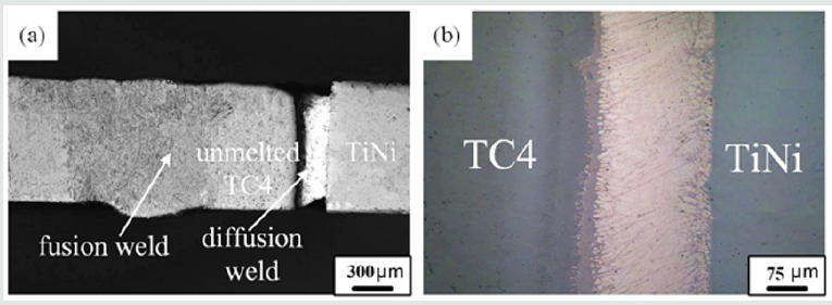
The optical microscopy image of the cross section of the joint is shown in (Figure 2a). The joint can fall into three parts: the fusion weld formed at the Ti alloy side, unmelted Ti alloy and the diffusion weld formed at the TiNi-Ti alloy interface. The fusion weld did not form Ti-Fe intermetallics due to the presence of unmelted Ti alloy. The average width of fusion weld, unmelted Ti alloy and diffusion weld was 1.8 mm, 0.35 mm and 0.17 mm, respectively. Because the microstructure of the fusion weld is quite different from that of the diffusion weld, the diffusion weld becomes black after corrosion. (Figure 2b) presents the optical image before corrosion of the diffusion weld. It does not present such defects as pores and macro-cracks. The unmelted part of Ti alloy acted as a heat sink absorbing a significant amount of energy from the welding pool and transferring it to the TiNi alloy side [20]. Hence, the filler metal of TiNi-Ti alloy interface had a high temperature during welding although it was not subjected to laser radiation. The temperature was high enough to promote atomic interdiffusion. This meets the temperature requirement for diffusion welding. Moreover, the local heating of the Ti alloy side caused uneven volume expansion and thermal stress was produced, which helped to obtain an intimate contact between the TiNi alloy, Cu-based fillers and Ti alloy surface. The high temperature and the intimate contact at the TiNi-Ti alloy interface provided favourable conditions for atomic (Cu, Zn, Ti, Ni) interdiffusion. Therefore, a diffusion weld was formed originated from atomic (Cu, Zn, Ti, Ni) interdiffusion at the Ti alloy-filler metal and filler metal-TiNi alloy interface. Additionally, the unmelted Ti alloy was beneficial to relieve and accommodate the thermal stress in the joint, which could help to improve the mechanical properties of the joints.

Figure 2: Macroscopic feature of the joint: (a) optical image of the cross section of the joint; (b) optical image before corrosion of the Ti alloy-TiNi alloy interface.

Lupinepublishers-openaccess-material-science-journal

Microstructure Analysis

The optical image of the fusion weld is shown in (Figure 3a), and no defects were observed in it. SEM image of the fusion weld is shown in (Figure 3b). The fusion weld mainly consists of acicular structure. The optical image of the diffusion weld at NiTi-Ti alloy interface is shown in (Figure 3c). It can be observed that, the diffusion weld contained three zones marked as Ⅰ, Ⅱ and Ⅲ sorted by their morphologies and colours. (Figures 3d, 3e and 3f)correspond to the three zones in (Figure 3c), respectively. The compositions of each zone (denoted by letter A-C in (Figure 3)) were studied using SEM-EDS. EDS analysis was applied to these zones to measure the compositions of the reaction products and the results are listed in Table 1. Based on the previous analysis, the microstructure of the diffusion weld was mainly composed of Cu-based fillers. The chemical composition of zone Ⅰ was consistent with the Cu-based fillers. Based on the EDS analyses results and Cu-Zn phase diagram, the main microstructure of zone Ⅰ was defined as β-CuZn phase. When the laser beam was focused near the Ti alloy-filler metal interface, the element diffusion occurs immediately between the base materials and filler metal and causes its component to deviate from the original component. The interdiffusion of Cu, Zn, Ti and Ni elements occurred at diffusion welding interface (Ti alloy-filler metal and filler metal-NiTi alloy). At this moment, the dissolution of Ti and Ni into the filler metal occurred under the high concentration gradient, which formed solid-phase reaction layer, and this reaction layer exists only in the smaller region of the NiTi-Ti alloy interface. As shown in, zone Ⅱ and zone Ⅲ were reaction layers formed by element diffusion. Based on Ti-Cu-Ni phase diagram, the microstructure of zone Ⅱ was defined as TiCu2+NiZn. Based on Cu-Ti-Zn phase diagram, the microstructure of zone Ⅲ was defined as Ti3Cu4+Ti2Zn3. Therefore, the main microstructures of diffusion weld were TiCu2+NiZn, β-CuZn and Ti3Cu4+Ti2Zn3.

Table 1: The chemical composition of each phase in joint C (wt.%).

Lupinepublishers-openaccess-material-science-journal

Figure 3: Microstructures of the joint : (a) optical image of fusion zone; (b) SEM image of fusion zone; (c) optical image of the diffusion weld; (b) SEM image of the zone I in Fig. 3c; (c) SEM image of the zone II in Fig. 3c; (d) SEM image of the zone III in Fig. 3c.

Lupinepublishers-openaccess-material-science-journal

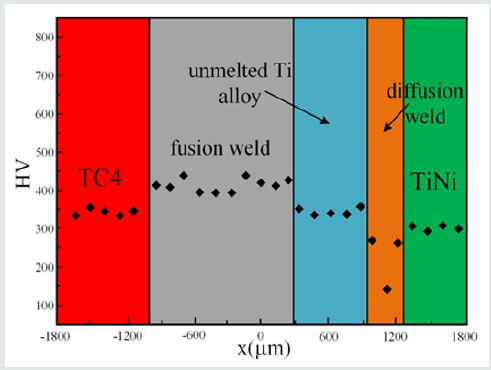
Figure 4: Vickers microhardness measurements at semi-height of joint (zero point situated in the center of joint).

Lupinepublishers-openaccess-material-science-journal

Tensile Tests and Fracture Analysis

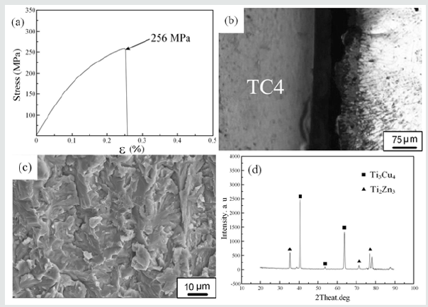
The maximum tensile strength of the joint was about 256 MPa (Figure 5a). The joint fractured in Ti alloy side of the diffusion weld during tensile tests (Figures 5b, 5c)shows fracture surface of the joint exhibiting typical brittle characteristics. Moreover, as shown in (Figure 5d), XRD analyses of fracture surface detected Ti3Cu4 and Ti2Zn3 phases. This confirmed the presence of Ti-Cu and Ti-Zn intermetallics at fracture surfaces. It should be noted that there was no Ti-Ni intermetallics in the brazed weld. Reaction layer at Ti alloy side in diffusion weld became the weak zone of the joint, which led to the failure in the tensile test.Based on the above results, the formation of Ti-Ni intermetallic compounds is avoided due to the presence of unmelted Ti alloy in the joint. Only a small amount of Ti-Cu intermetallic compounds is formed in the reaction layer at the NiTi-Ti alloy interface. Due to the rapid heating and cooling speed of laser welding, the holding time at high temperature is short, and it is easy to form a narrow reaction zone at the NiTi-Ti alloy interface. In addition, higher cooling rate inhibited the growth of dendrite structure in the reaction zone. Therefore, it is easy to obtain fine microstructure in the reaction zone, which is conducive to reducing the brittleness of the reaction layer. The results show that the formation of narrow reaction layer and fine metallurgical structure at the interface is one of the main reasons to improve the joint strength.

Figure 5: Tensile test results of joint: (a) Tensile test curve; (b) Fracture location; (c) SEM image of fracture surface; (d) XRD analysis results of fracture surface.

Lupinepublishers-openaccess-material-science-journal

Conclusion

The possibility of welding processes for connect TC4 Ti alloy to NiTi alloy with Cu-base filler metal was studied. The main conclusions are presented below. without filler metal, For joint with a laser beam offset of 1.2 mm for Ti alloy, the unmelted Ti alloy was selected as an barrier to avoid mixing of the NiTi alloy and Ti alloy which eliminated the formation of brittle Ti-Ni intermetallic in the joint . A diffusion weld was formed at the NiTi alloy-Ti alloy interface with the main microstructure of TiCu2+NiZn, β-CuZn and Ti3Cu4+Ti2Zn3. A great amount of atomic diffusion occurs at the NiTi-Ti alloy interface during welding, and the thickness of diffusion weld can reach hundreds of micrometres. The tensile resistance of the joint was determined by diffusion weld. The maximum tensile strength of joint was 256 MPa.

For more Lupine Publishers Open Access Journals Please visit our website:

 wt u have given that link add For more Modern Approaches on Material Science articles Please Click Here:https://lupinepublishers.com/material-science-journal/

Happy Thanksgiving 2022!!!

                      Thanksgiving is a joyous invitation to shower the world with love and gratitude. Forever on Thanksgiving the heart wil...